Attaching Screen and RFID Reader Frames To Tapwall
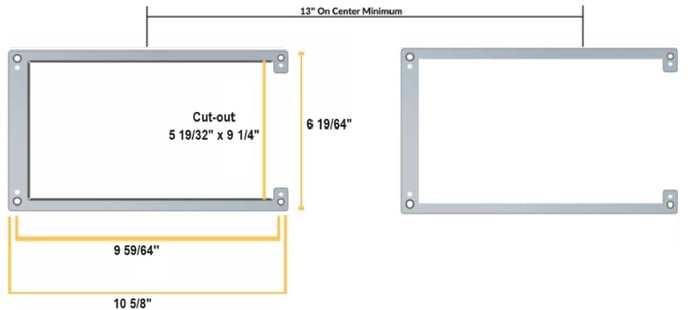
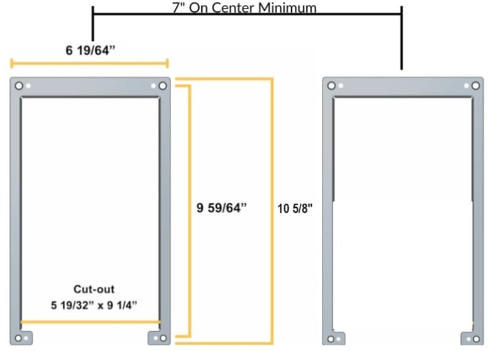
Use #6 Screw Flat head screws to mount the Screen and RFID reader frame to the Tap Wall. Screw depth will depend on the backing materials used.
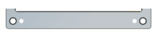
A mounting tool, pictured below, is included on every frame. Position this tool on the open end of the Screen Frame when attaching to wall to keep the Screen Frame square.
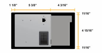
Screen Cutout and Mounting Frame Dimensions
Ensure that the screen cutouts are centered over the tap handle "sets."
Landscape: 1 - 4 Taps per screen
Portrait: 1 Tap per screen
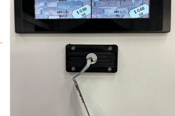
RFID Reader Mounting
To maintain ADA compliance, this hole must be below 48".
A 3/4 - 1" hole must be drilled below the screen and the RFID holder must be mounted on the finished tap wall surface using #6 flathead screws.

The RFID reader ribbon cable will pass through this hole and connect to the back of the screens.
The total length of the RFID reader cable is 90".
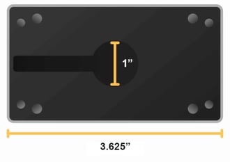
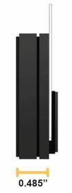
RFID Dimensions

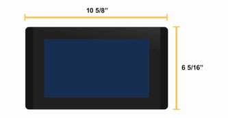
Tapwall Screen Dimensions
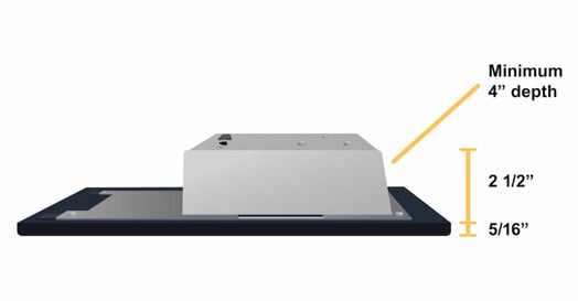
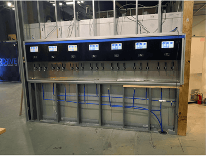
Tap Wall Construction Considerations
| There must be a cavity with 4″ of depth (minimum) for the screens to be installed into your Tap Wall Be sure to adhere to the screen spacing requirements outlined above. RFID Readers and Tap handles should be no higher than 48” for ADA compliance. 120V Power outlets should be located within 6’ of the screens and unobstructed access between the 120V outlet and the screen that will be receiving power. I.E. no studs blocking the cable drops. Holes must be cored into the cooler behind the screens so the control valves and flow meters can be wired into the back of the screens. |
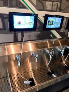
The photo above is a Tap Wall buildout with a Direct Draw Draft System. For Direct Draw Systems, the simplest way to provide power and network access is to locate the Network Switch and UPS Battery backups on top of the cooler. |