
The Valves and Flow Meters control and measure the dispensing of beer in ounces at the taps.
Pay close attention to how these are installed. The Valves are directional, the Flow
Meters are not. Proper installation of the control device has a direct impact on the success of
your installation.
PourMyBeer will provide valves, meters, and fittings for your Draft System Installation
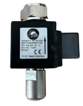
| Control Valves |
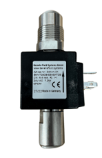
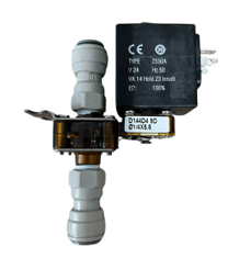
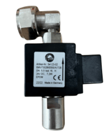
Long Draw Integrated Valve Isolated Valve
Direct Draw 90 Degree Valve Straight Valve with 5/8" nut
|
| Flow Meters | 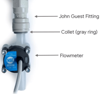 |
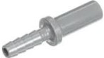
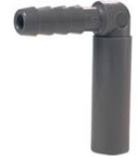
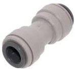
| Installation Fittings for the Valves & Flow Meters** **Fittings will vary due to the tubing size and material selected for your Draft System. Connect your Installation Coordinator with your Draft Technician so we can ship the correct fittings with your order. |
Long Draw Fittings: use ⅜” x ¼” Smooth to Barbed fittings for attaching the Long Draw Valve Assembly to your beer lines.
Direct Draw Fittings: use ⅜” x ¼” 90 degree Union Fittings fittings to attach to your beer lines.
Union Fittings use 3/8" fittings to fit over the flowmeters
|
Self Pour Draft System Requirements, but not included
|
Fobs (Foam on Beer Detectors): |
 |
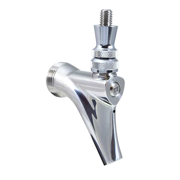
| Trigger Tap Style Faucets (recommended): These are binary (on / off) faucets that only allow the taps to be open or closed. This prevents a foamy pour from only slightly opening the tap. |
 |
| Restriction: There should be enough restriction and pressure in the beer lines to result in a 1-1.5 second per ounce pour time (about half the speed of a normal bar faucet.) We need the flow of beer to be slowed way down for the average customer. |
Our flowmeter and valves add 1lb of restriction into the line. Pressures are typically around 22psi. |
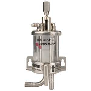
| Blended Gas is required. We recommend the following gas blender models from Micromatic | i. MM-200 ii. MM-200-LD iii. MM-200-60-40-LD *Consult with your Draft Technician and C02 provider to determine which blender will work best for your application. |
| ADA: Tap handles and RFID Readers should be 48” or less to maintain ADA compliance. |
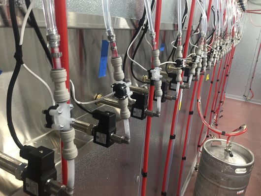
Placement of Valves and Meters (all designs)
Beverage flow should follow this path:
Keg > Fob > Flow Meter > 4-6" of 1/4"Poly Line> Valve > Faucet.
*The Valve and Flow Meter assemblies MUST be installed below the taps and within 100 feet of the screen controlling the Flowmeter/ Valve.
*Valves & Flow Meters MUST be installed into a Walk-In Cooler, Kegerator, or Remote Cooler.
*Valve and Flow Meters CANNOT be installed in Trunk lines or Pythons.
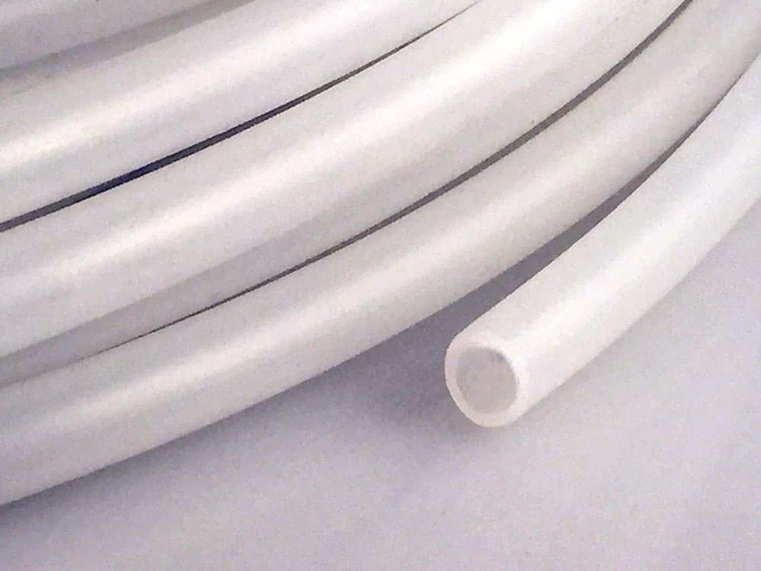
| ¼” ID Poly Should be used for the 4” – 6” of space between the valve and flowmeters. This line will plug directly into a Union Fitting or the Integrated Direct Draw and Long Draw Valves. |
 |
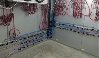
Long Draw Systems
 |
-JPEG-1.jpeg?width=313&name=IMG_3478%20(1)-JPEG-1.jpeg) |
*Beer Lines between the Control Valves and the Faucets must not be higher than the Faucet or there will be a siphoning issue (see bottom of page).
*Valve Assemblies must be less than 100’ from the Pour My Beer Screens. Anything greater will result in signal loss of the Flowmeters.
*4” - 6” of ¼” poly tubing between the Valve and Flow Meter.
2” minimum spacing between each assembled Valve & Flow Meter.**
*Customer supplied CAT6 Line run from each Valve assembly to each Screen (numbered)
*Number each valve and flowmeter to the corresponding Tap for Identification prior to installation.
Failing to maintain adequate spacing between the Valves & Flow Meters will result in electrical interference of the Flow Meter. This causes “phantom pours” where the screen will count even though nothing is being poured from the tap.
Long Draw - Modified with Valves & Flow meters in a Remote Cooler
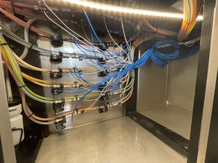
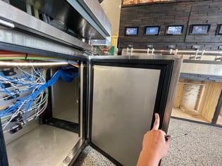
Ex.) The Walk In Cooler was 200’ away from the Beer Wall at this location. A mini-cooler was
built below the taps to house the valve assemblies. This prevented siphoning***(see bottom of page) and provided ease of access for maintenance.
*Beer Lines between the Control Valves and the Faucets must not be higher than the
Faucet or there will be a siphoning issue (see bottom of page.)
*Valve Assemblies must be less than 100’ from the Pour My Beer Screens.
*4” - 6” of 1⁄4” poly tubing between the Valve and Flow Meter.
*2” minimum spacing between each assembled Valve & Flow Meter.
*Customer supplied CAT6 Line run from each Valve assembly to each Screen (numbered)
*Number each valve and flowmeter to the corresponding Tap for Identification prior to installation.
*Link to sample cooler setup. 24 valve and meters assemblies will fit in the 48” version of
the Infinity IBCRR-2D Model
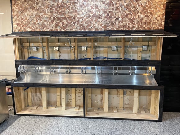
Direct Draw
Example) Valves are threaded directly onto the shanks. The stainless steel
shadow box is built directly into the beer wall so there is no air gap or
unconditioned space for shanks. This keeps the beer at the appropriate temperature.
*Shadow Box - to prevent foam.*
*Beer Lines are connected directly to the shanks.
*4” - 6” of 1⁄4” poly tubing between the Valve and Flow Meter.*
*2” minimum spacing between each assembled Valve & Flow Meter.
*Number each valve and flowmeter to the corresponding Tap for Identification prior to
installation.
*If a Shadow Box is not going to be used the taps will have to be purged before operation to remove foam.
**Failing to maintain adequate spacing between the Valves & Flow Meters will result in electrical interference of the Flow Meter. This causes “phantom pours” where the screen will count even though nothing is being poured from the tap.
Common Installation Problems
Siphoning
Siphoning occurs when the trunk lines or pythons travel above the height of the taps after the
control valve and before the faucet. The only way to prevent siphoning is to run the trunk lines
low out of the cooler, below the taps, with a rise up to the tap wall. Another method is to use a
pass-through kegerator / refrigerator to house the Valve & Flow Meter assemblies.
Phantom Counting
Phantom Counting or “meter creep” occurs due to electromagnetic interference between a Valve
& Flow Meter. This can be prevented by installing 4”-6” of 1⁄4” poly line between the Valve &
Flow Meter.
Leaks
Leaks at the Valve & Flow Meters can be caused by a compromised O-Ring seal or if the fittings
aren’t seated properly. Try to reseat the fitting or replace to stop the leak.